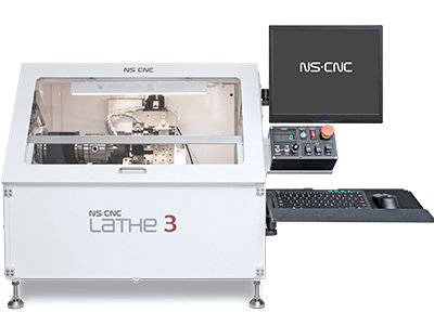

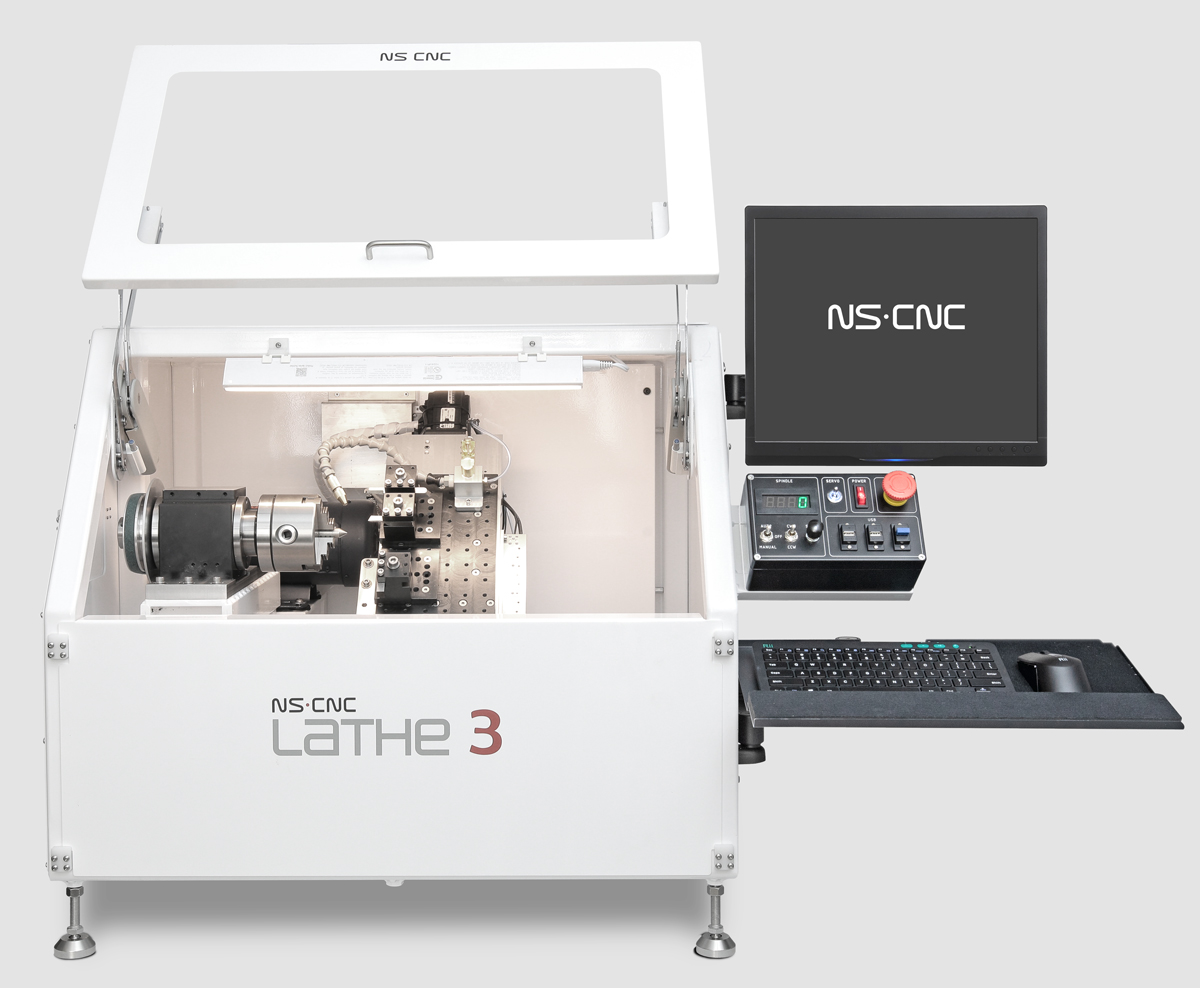
Lathe 3
Third-generation 3-axis CNC lathe. Built for microscopic turning — watches, scientific instruments, jewelry, electronic components. Full CNC capability in a fully enclosed tabletop unit.
Third-generation 3-axis CNC lathe. Built for microscopic turning — watches, scientific instruments, jewelry, electronic components. Full CNC capability in a fully enclosed tabletop unit.
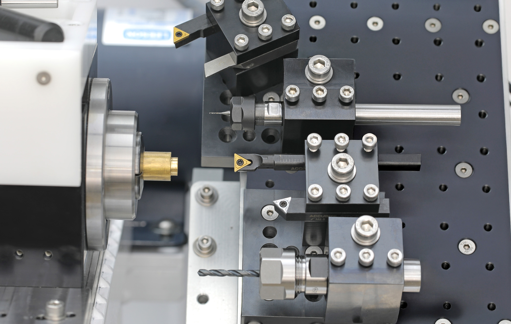
Conventional lathes operate on two axes — Z and X. The Lathe 3 adds a Y-axis, tilted 45° relative to X. Tool height adjustments happen automatically during program execution, not manually at setup. Multiple tools stage at different heights on the gang plate and are addressed individually without operator intervention. The 45° X-axis tilt simplifies tool height relationships relative to the spindle centerline and improves operator access on small parts.
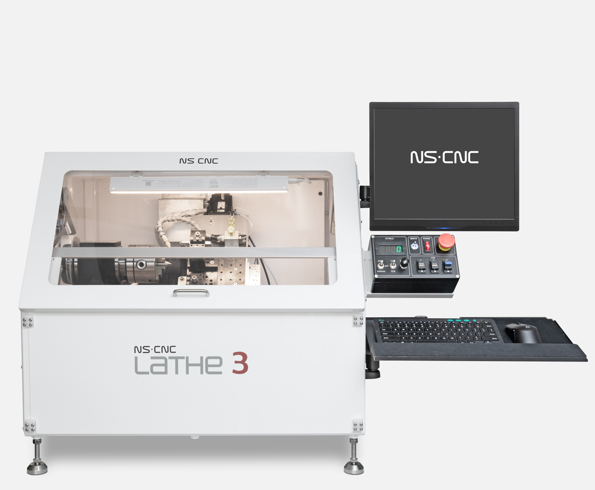
These are third-generation mini lathes manufactured by our company. These machines are essential for precision turning of microscopic parts used in applications such as watches, scientific instruments, jewelry, electronics, and more. As with all our machines, this model is a compact, fully enclosed tabletop unit. Despite its small size, it delivers powerful performance, capable of handling tasks typically reserved for larger CNC lathes.
Placeholder body copy for the fourth tile — replace with real content.
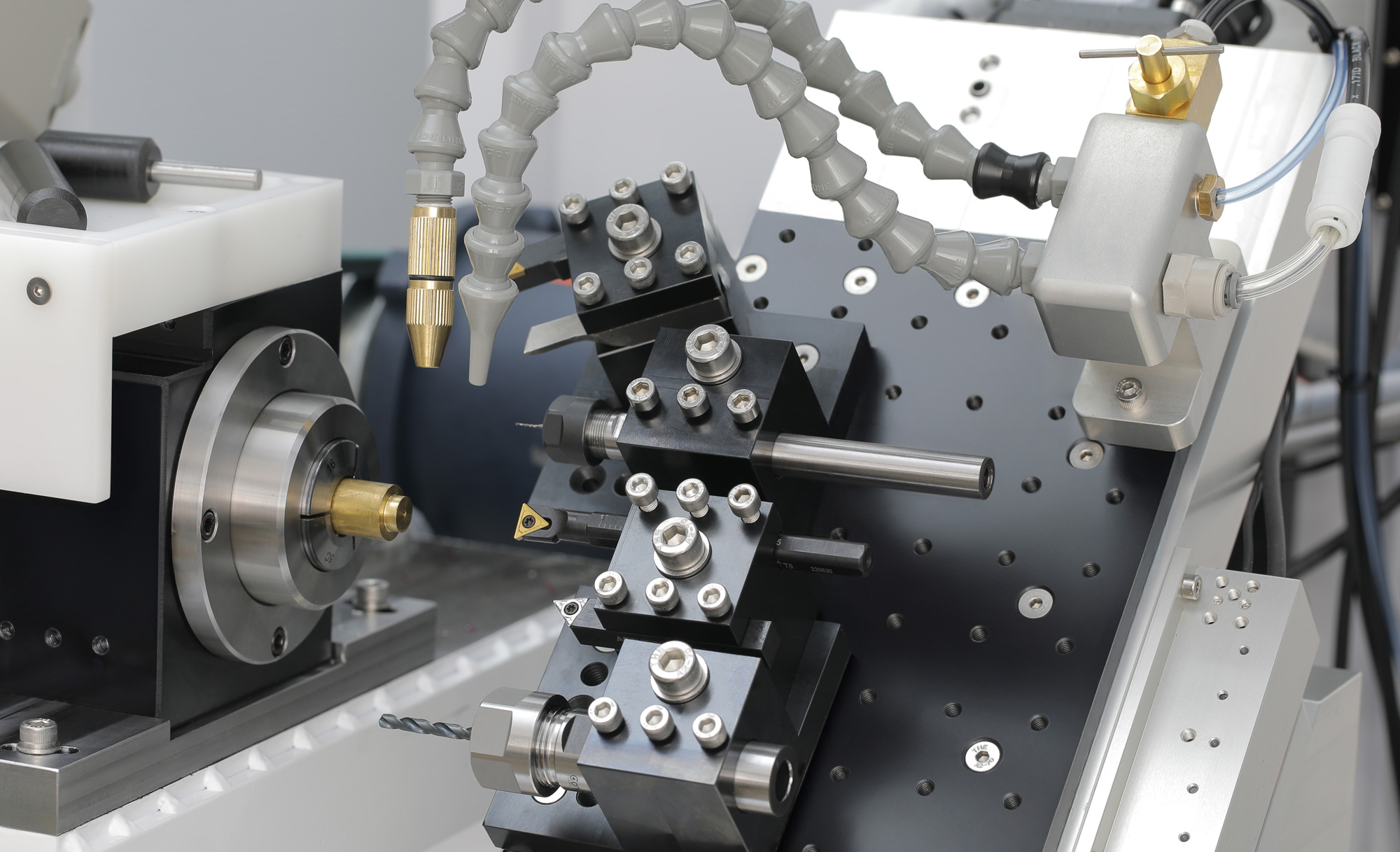
Gang tooling arranges tools in fixed sequence on the cross-slide. Tool changes execute by carriage repositioning — fast, rigid, mechanically simple. Correct for small-diameter, short parts where multiple tools are needed and a tailstock is not. For large-diameter parts requiring rear approach or a tailstock, turret tooling on a larger machine is the appropriate choice. The Lathe 3 is built for the class of work where gang tooling excels.
Placeholder body copy for the sixth tile — replace with real content.
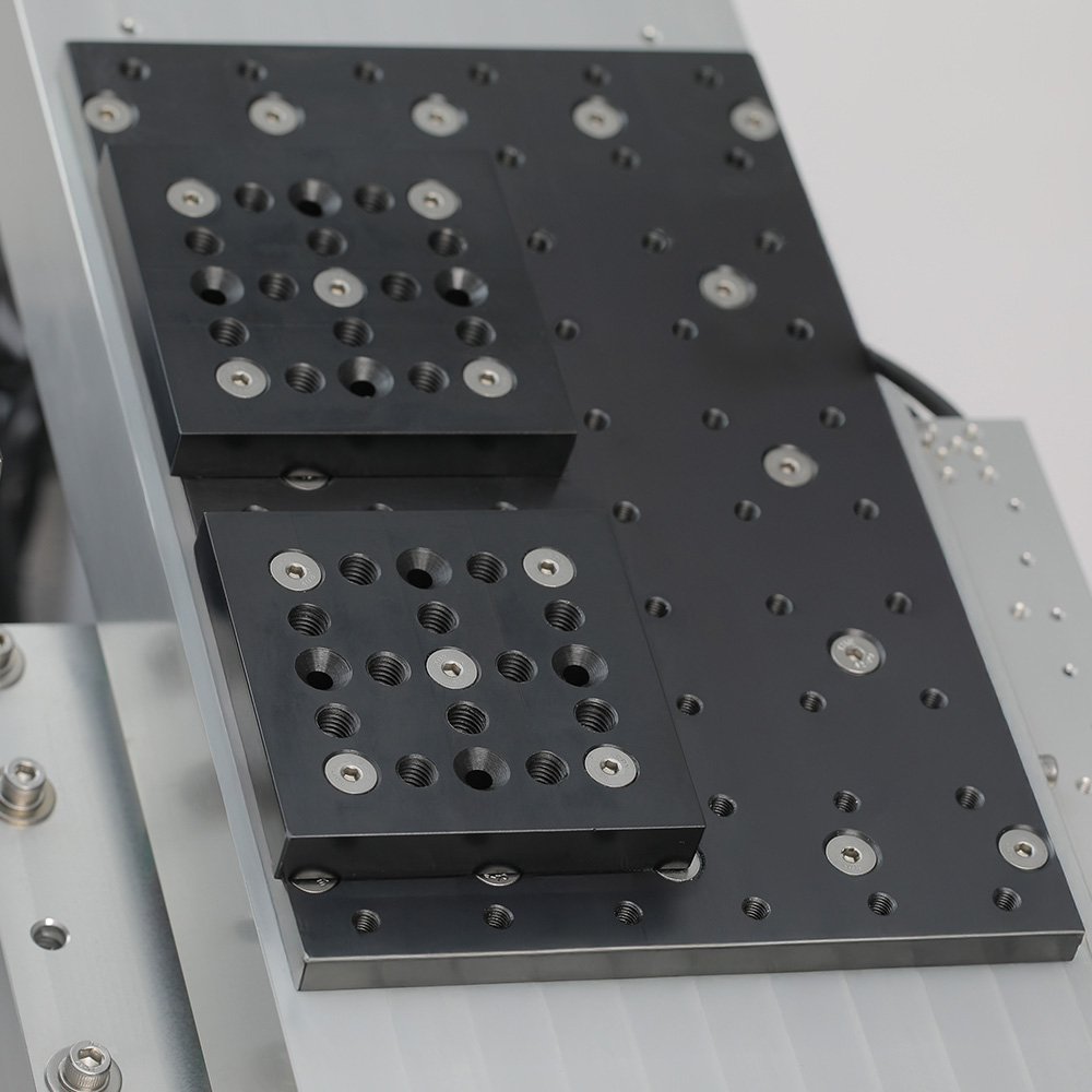
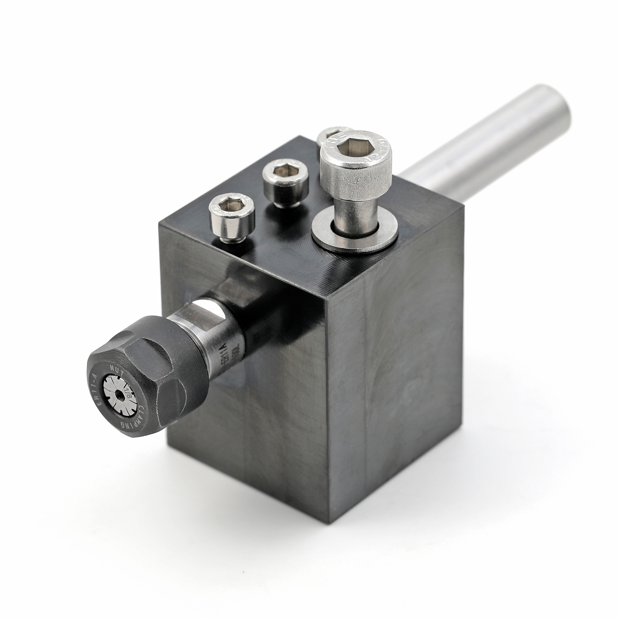
The machine features a versatile tool-holding system, utilizing individual posts with slots or holes to securely fix each tool in place. These posts can be adjusted to different angles relative to the coordinate axes to accommodate various machining needs.
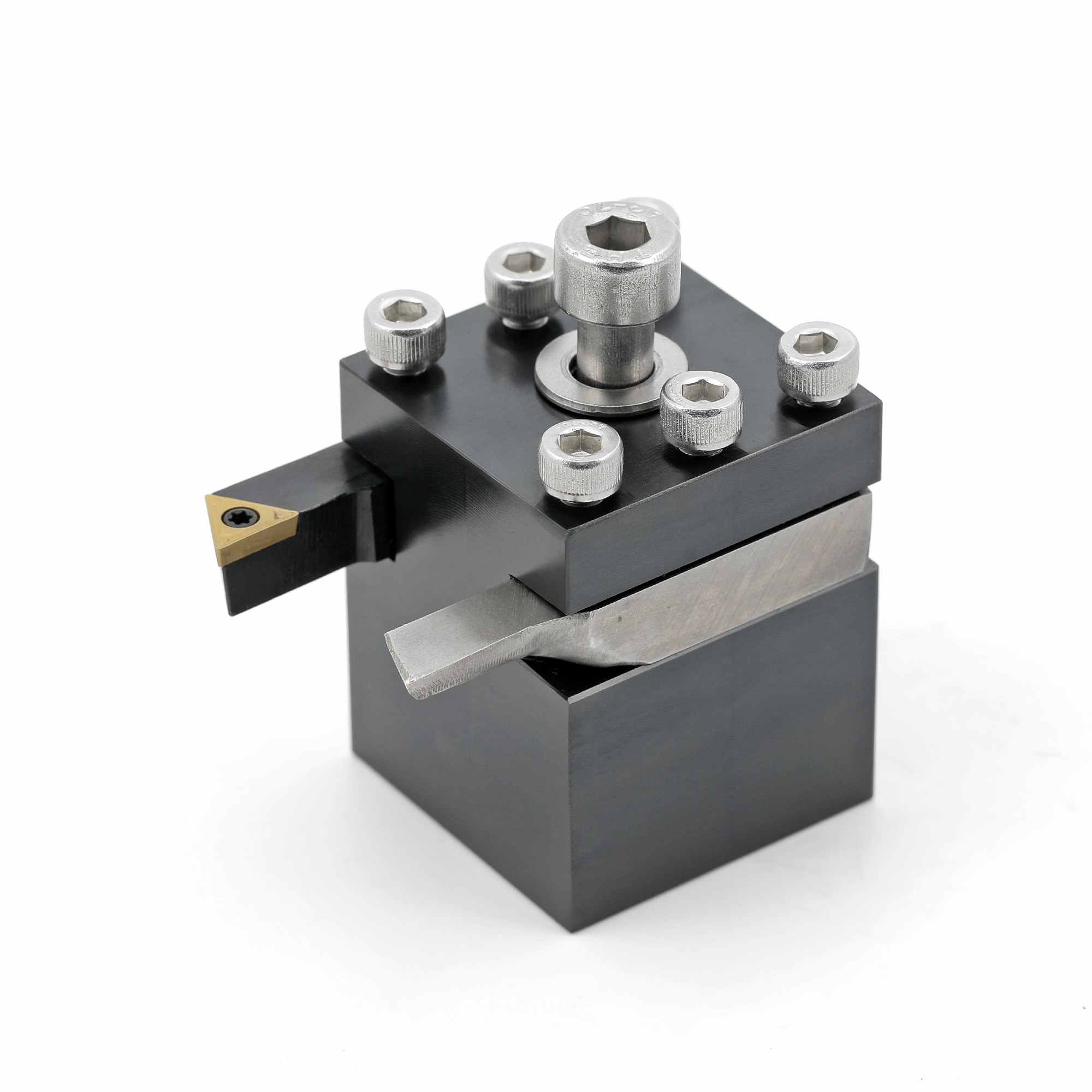
The posts are mounted onto bases, which are securely fastened to the X carriage table. This design allows for flexible positioning, enabling the tools to be arranged in any configuration that best suits the operator’s requirements.
In addition to the standard post configurations, the company is also able to manufacture custom posts tailored to specific dimensions or designs, based on customer specifications, to support specialized tooling needs.
Placeholder body copy for the tenth tile — replace with real content.
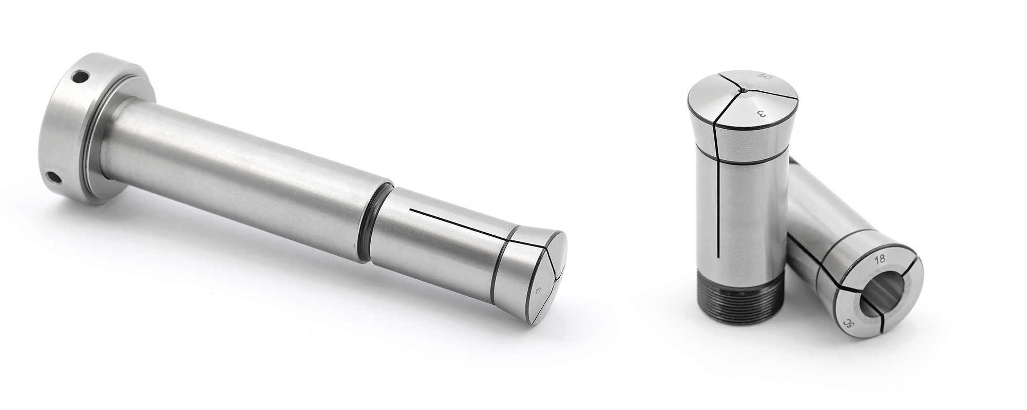
The 5C collet installed in the Headstock of the lathe is the most popular and oldest, which appeared with the first lathe at the end of the 19th century. Brothers Franklin and Henry Hardinge, founders of the Hardinge Brothers Inc., created the first watchmaker lathe, the Hardinge Cataract Lathe, which used #5 Back-Gear Head with collet.
Since then, the name 5C (#5 Cataract) has appeared. The “Cataract” name came from the river cataracts outside the original Hardinge factory in Chicago. The collet design turned out to be very successful and has not changed for the second century. Along with size #5, other sizes of the C series appeared.
The 5C collet became an industry standard for lathe. 5C collets range from 0.5 mm (that’s 0.0196″) capacity to 1-1/16″ round; 5C collets hold up to 3/4″ square and 29/32″ hex. Generally, the 5C collet is the subtype of chuck that can quickly form the collar around the object to occur. Then it will apply a strong clamping force on the object after tightening. It can be helped by tapering the outer collar. Finally, lathe collets are useful for holding the tool or workpiece. The picture on the right shows collets of different sizes. The picture below shows a collet with a bar that is used to clamp it at the back.
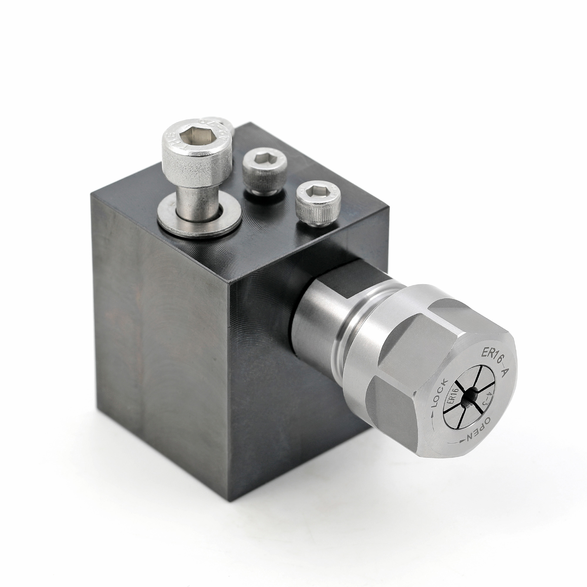
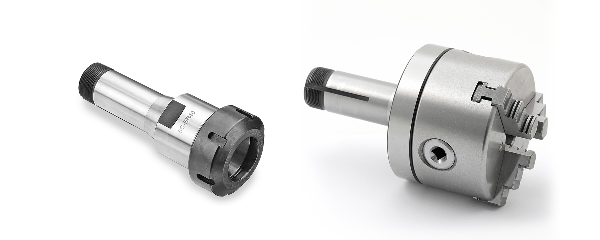
The 5C collets are useful and highly accessible in metric and inch dimensions. You can use the wide range of collets with standard 5C collet equipment, rods, and other producers’ 5C equipment. For example, a 3-jaw clamp (Picture on the right) or an adapter for collets of another very popular type of ER Collet (Picture on the left)
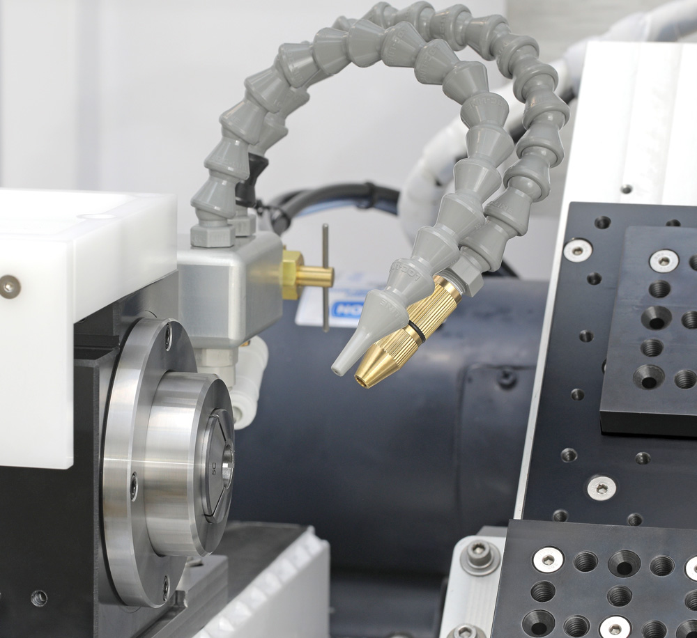
The Lathe is equipped with a dual cooling system. You can feed a regular coolant into the working area through a regular plastic nozzle. This is a water-soluble oil that wets the workpiece, cools the tool and prevents dust from spreading. The coolant can be supplied either continuously or in a pulsating mode. This can be adjusted in the control program. The pulsation can be with intervals from 0.1 to 5.0 seconds.
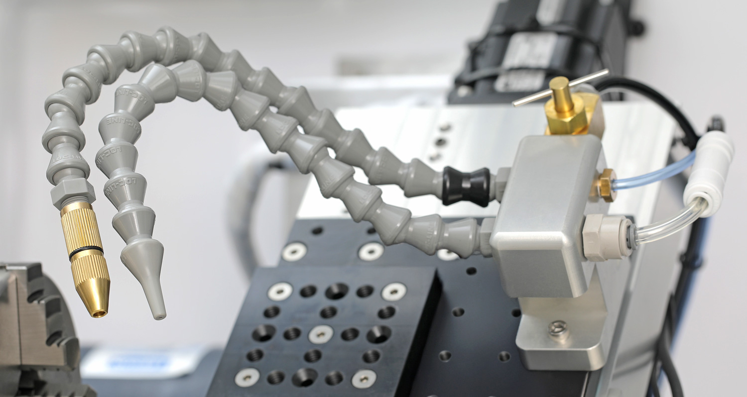
Through a nozzle with a brass tip you can supply a mist of air mixed with coolant. This allows you to blow away chips along with moistening the working area. The mist supply is regulated by a manual valve. The nozzles can be installed in two positions: stationary, next to the spindle, or movable, on the X carriage. Which nozzle position, mist or coolant, which type of coolant depends on the material being processed, cutters, turning strategies and many other parameters. Under certain conditions, you may not need a coolant at all. These and many other questions can be answered by our specialists.
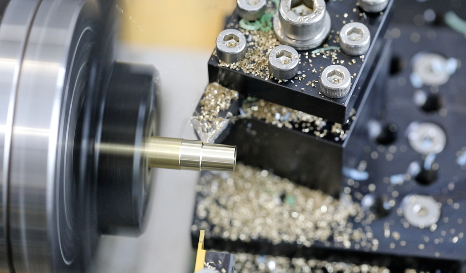
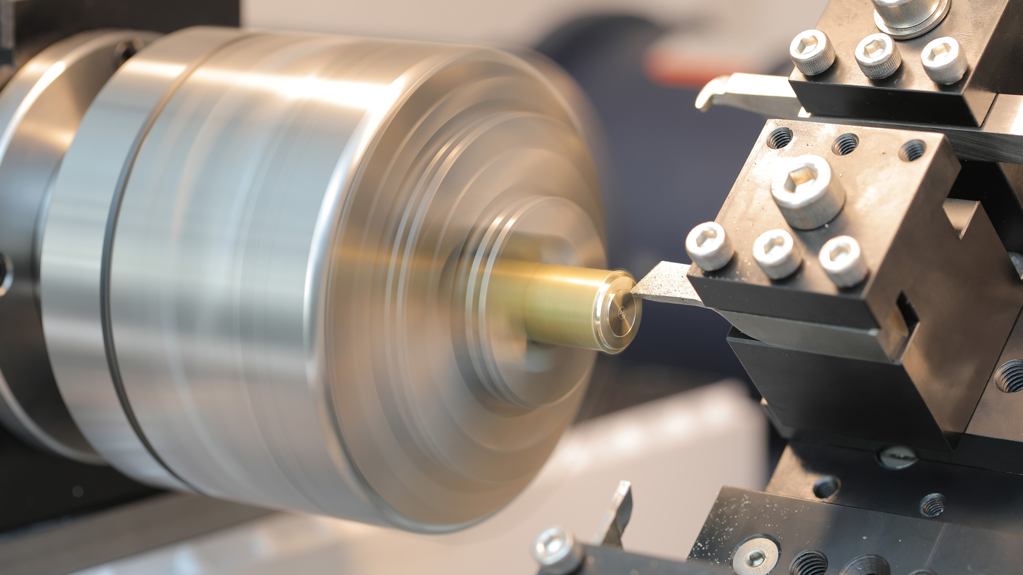
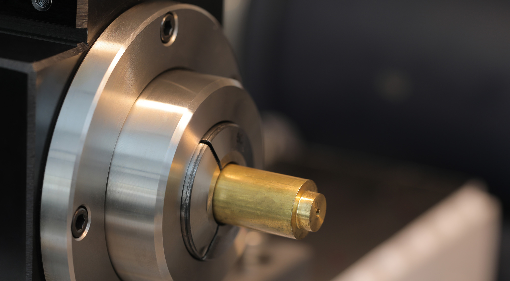
A brass bar clamped in a 5C collet. The first tool on the gang plate engages the workpiece and removes material to establish the outer diameter.
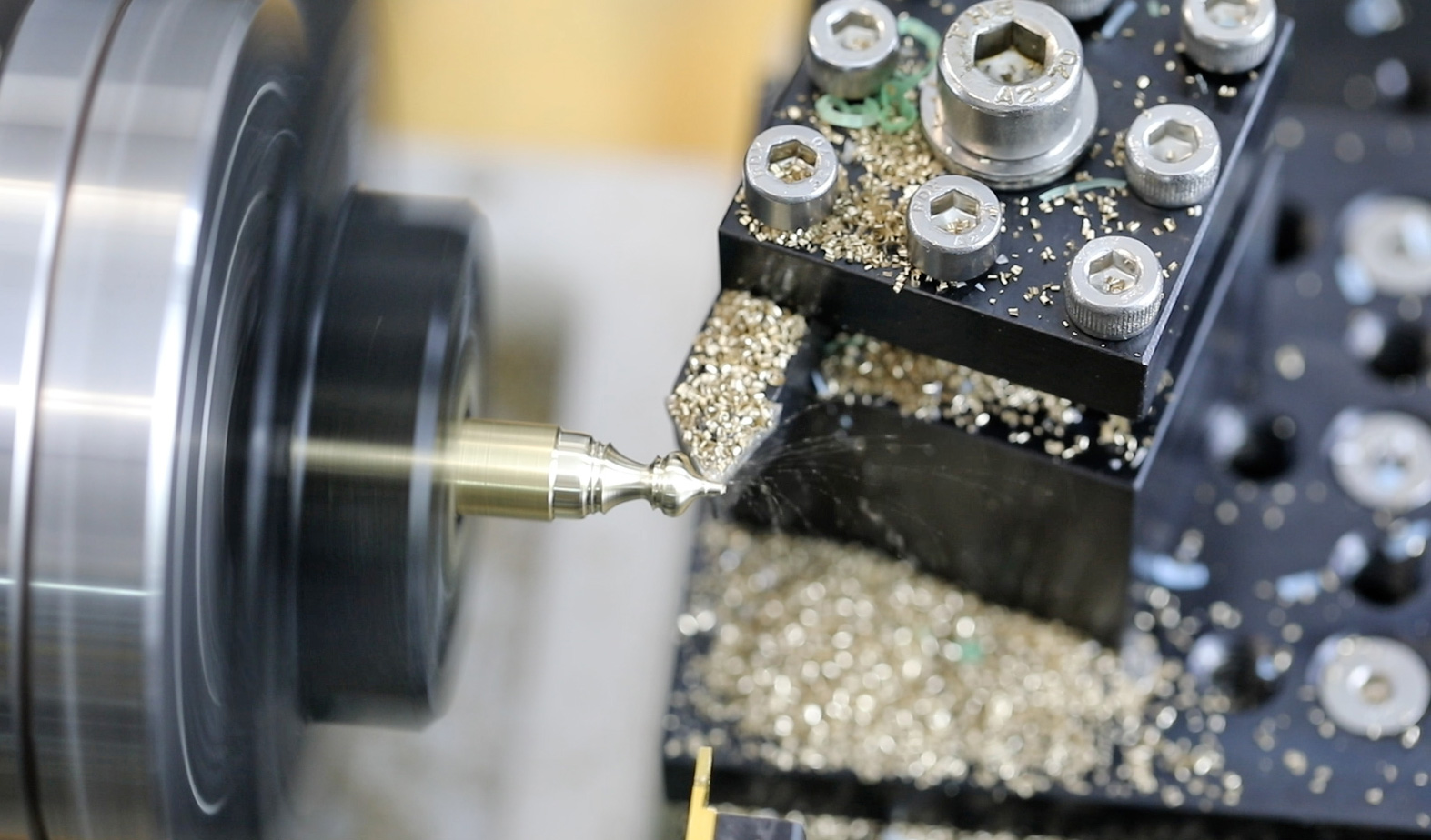
A profile cutter generates the outer contour. Stepped diameters and curved sections appear as the tool moves along the Z axis.
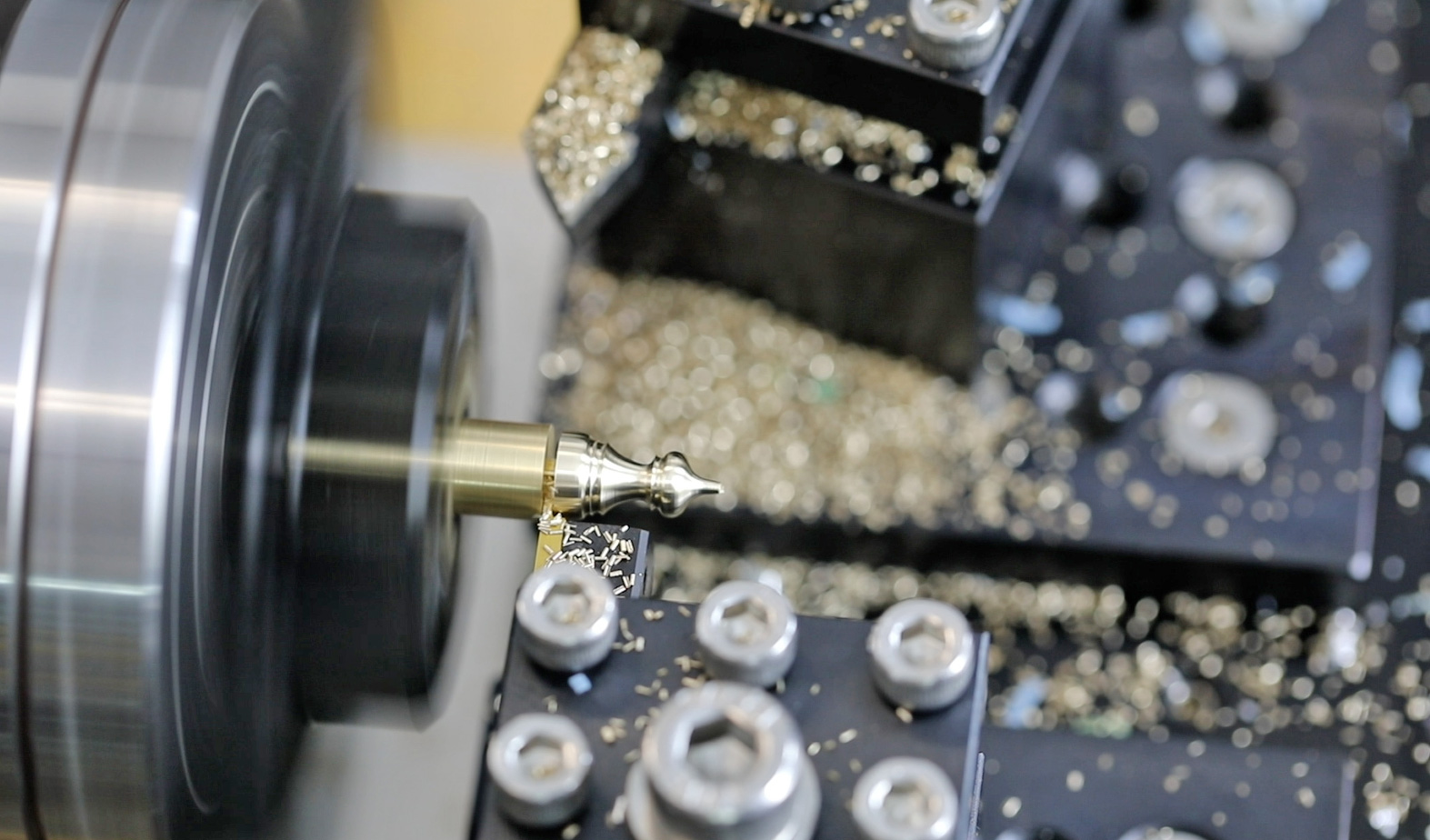
The last tool finishes the upper section — point, sweep, and base — completing the shape. The piece remains attached to the bar stock until parted off.
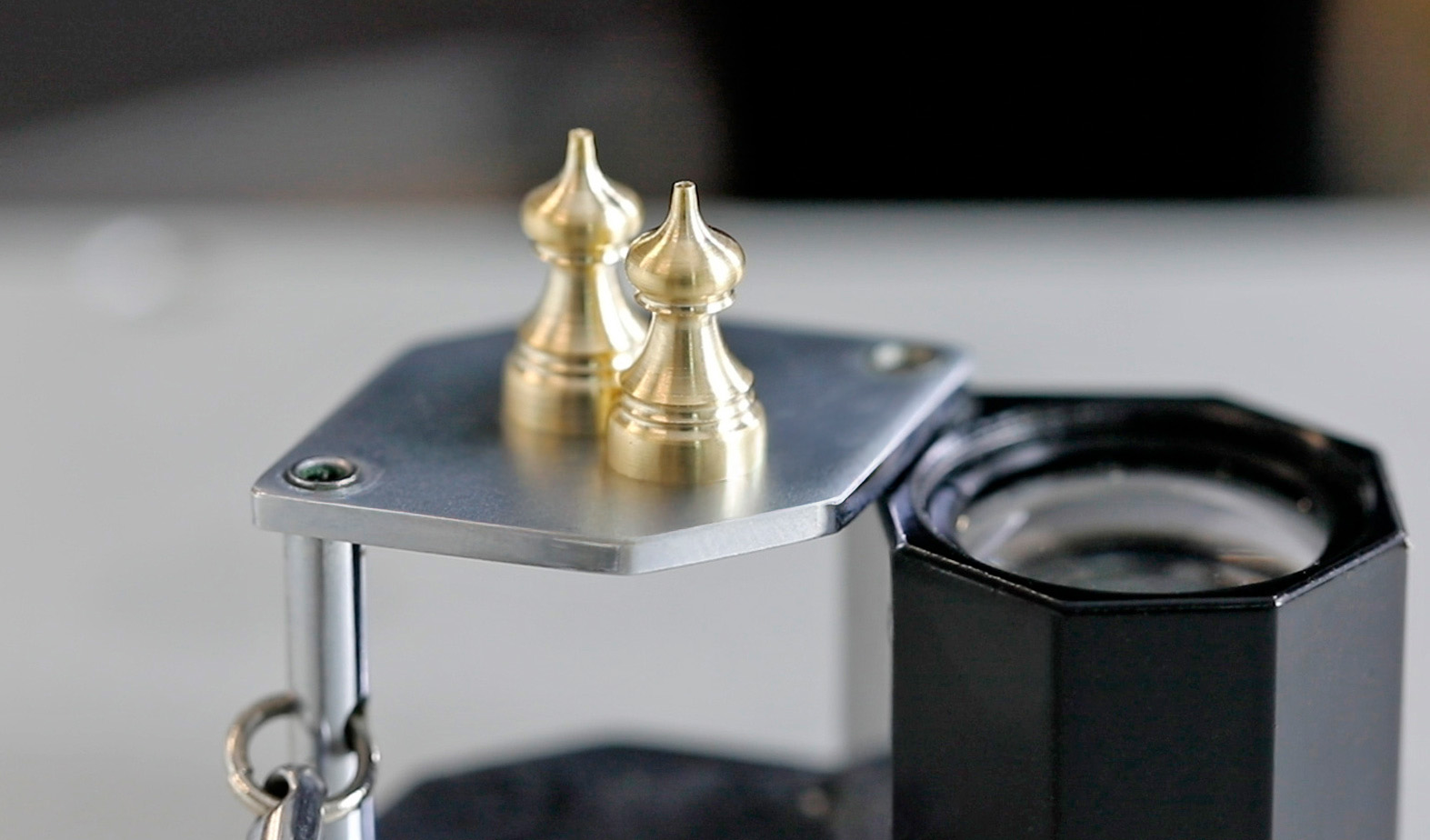
Two brass finials shown next to a 10× loupe for scale. Each piece cut from a single length of brass, no secondary operations.